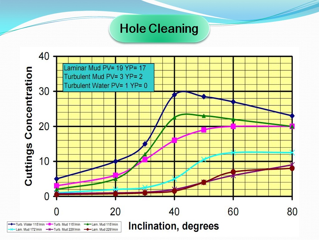
الصفحات

Showing posts with label Horizontal Wells. Show all posts

Tuesday, March 27, 2012

Drilling and Completion of Multilateral Wells

MULTILATERAL 
TERMINOLOGIES 
Laterals are wellbores drilled from the main wellbore. 
Wellbores drilled from a horizontal lateral into the horizontal plane  are branches, those drilled from horizontal lateral into the vertical plane are splays.
A multilateral well can follow different well trajectories: horizontal or deviated Junctions are the intersections of the laterals with the main wellbore or of the branches and splays with the lateral

Multilateral Completion Systems  
Sperry-Sun drilling Services Company has developed two distinct completion systems for multilateral well bores which have full-open through-bore and re-entry capabilities. These systems are:
Lateral-Tie Back System, LTBS.
Retrievable Multi-Lateral System, RMLS.
 
British Petroleum Co. (BP), has another system that is called "SRS", Selective Re-entry System for existing casing.
This system was developed by Weatherford Services Co.
The Lateral-Tie Back System, LTBS
This system consists of six main components
1.Pre-milled casing window joint.
2.drilling whipstock..
3.Lateral liner hanger. 
4.Lateral liner running tool.
5.Cementing whipstock if drill with cemented Junctions.
6.Re-entry whipstock.
Retrievable Multi-Lateral System, RMLS 
The RMLS consists of four components
1.Casing window system.
2.Retrievable deflection tool (whipstock) incorporating.
3.Lateral liner transition joint.
4.Washover assembly.
Selective Re-entry System of Multilaterals
Technologies were not developed that enabled drilling
multilaterals into different producing reservoirs.
SRS is the solution for increasing
oil production and reserves
from existing wells.
Technology Advancement Multilateral (TAML) 
Classified multilateral wells into seven categories (six levels with one sublevel) and provided a common language for operators and service companies to use when discussing multilateral completions.
The definitions of the TAML levels were based on the amount and type of support and functionality provided at the junction in the well where one lateral wellbore merges with the main bore or with another lateral.
Technology Advancement of Multilaterals (TAML) levels 
Level 1:
 
 is an open-hole lateral from an openhole mother bore.
There is no mechanical or hydraulic junction involved.
Carried out in consolidated formation as barefoot completions.
widely applied in the United States, Canada, Europe, and the Middle East, with up to six lateral having been drilled from mother bore.

 
Level 2
 
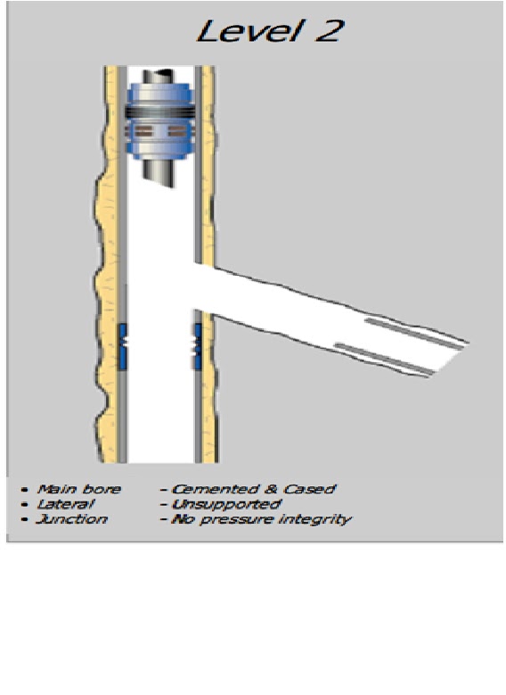
 main bore is cased in cemented and the lateral bore is open.
The completion is economical, allows selective production, and can be carried out in standard casing sizes.
United Arab Emirates wells have proven successful candidates for level 2.

 
Level 3:

 the main bore is cased and cemented, and the laterals are cased but not cemented.
The lateral liner is mechanically anchored to the main bore using a liner hanger.
level 4: 
 
both the main bore and laterals are cased and cemented to provide mechanical junction integrity.
can be simple, or they can be the basis for more complex systems such as dual packers completions, single string selective reentries and single strings with lateral entry nipples.
 
Level 5
 
 Sealed junctions multilaterals
are necessary for reservoir management
and to handle complex geology in well
environments with multiple pressures,
fluids, and the rock strata.

In these cases, pressure integrity is necessary to prevent junction collapse, due to pressure drawdown.
Full hydraulic and mechanical pressure integrity at junction are achieved with completion.
 
Level 6
 
 one in which junction pressure integrity is achieved with the casing and not by cement, which is not acceptable.
The entire junction is an integral part of the main bore casing string.
The first and most widely used level 6 system is the formation junction system.
The system is run in a perforated mode as part of a standard casing or liner string, then reformed down hole using swaging technology.
Conventional drilling, completion, and cementing techniques are used to finish construction and completion of well bore


watch video

http://oiltube.blogspot.com/2012/03/drilling-and-completion-of-multilateral.html


read more "Drilling and Completion of Multilateral Wells"

New Strategies for Designing the Horizontal Well Profiles


There are three
sections, namely:
1.   Vertical section: It is drilled from sea bed (mud  line) until KOP (the point  where deviating or sidetracking begins).  

2-Turned (Curved or angle-build) section: It is drilled from KOP to the end-of-curve (EOC). This section includes the first-build arc, the straight tangent, the second-build arc.

3. Horizontal section: It is drilled from the end of second-build arc or the end-of-curve (EOC) to the end of the proposed distance to be drilled horizontally in the pay zone, in accordance with the type of the horizontal well to be drilled.

The design of horizontal well based on three method:-

1-The simple tangent build curve method:-

The three major sections that form a horizontal well may be designed as follows:-
1-The build-radius of the first-build arc:
R=5730/B
2-Height of the first-build arc:
  D1=R(sin I2-sin I1)
3-Height of the straight-tangent:
       D2 = L2 Cos I2
4-Height of the second-build arc:
D3=R( Sin I3 - Sin I2).
5-The length of the first section of horizontal well = KOP
KOP = TVD D1 - D2 - D3
6-The displacement of the first-build arc:
H1 = R ( Cos I1 - Cos I2)
7-The displacement of the straight-tangent:
H2 = L2 - Sin I2
8-The displacement of the second -build arc:
H3= R( Cos I2 - Cos I3)
9-The length of the first-build arc:
L1 =100(I2 - I1 )/B
10-The length of the second-build arc:
L3=100(I3 I2)/B
11-The measured depth at the end of the first-build arc:
MD1 = KOP + L1
  12-The measured depth at the end of the straight tangent:
MD2 = MD 1+ L2
  13-The measured depth at the end of the second build arc:
MD3 =MD2 + L3
*The length of the second section =
L1 + L2 + L3 = MD3 - KOP
 
2-circular arc method:-
  It is a special design is based where,
R=H=TVDTEP-TVDKOP
   Thus. BUR may be determined as   follows:
BUR=5730/R
  =5730/(TVDTEP-TVDKOP )


Circular arcs are usually drilled only in areas where target entry point (TEP) and directional performance are well known
EX:-the Austin Chalk-amorphous limestone

3-Compound build curve method:-
This method have more than one planned build up rate and one or more tangent sections  where, different build up rates will be designed for the upper and lower sections.
EX:-a 4°/100 ft build rate may be used in the
upper section followed by a 8°/100 ft build up rate below the tangent section.
 
Accordingly, the recent advance for selection of the appropriate well profile is a function of the following,

1-Vertical depth of KOP and target selection. This KOP is selected based on hole problems, casing set depths, BHA performance, ROP, . . . etc.
2-Horizontal displacement to target entry point (TEP).
3-Completion design.
4-Formation evaluation program.
5-Hole size in the reservoir.
Thus, the optimum KOP should be selected based upon the following:

1-Minimizing hole problems.
2-Minimizing the amount of hole open during directional drilling operations.
3-The planned casing set depths.
4-The performance  of directional  drilling  assemblies  within  various formations.
5-The expected drilling rate within the various formations.
After selecting the optimum KOP, the vertical depth to the target can be determined as mentioned before. This will determine the build radius options available. These options should be refined by considering horizontal displacement to the target entry point (TEP). If the planned profile is compatible with the completion, evaluation program, and desired hole size, the profile selection is complete. If a parameter is not compatible, a design parameter must be altered or compromised, as shown in Table


read more "New Strategies for Designing the Horizontal Well Profiles"

Horizontal Drilling Problems


WOB (Weight On Bit)
Conventional bit weight for efficient drilling is about 2000-5000 lbf per inch of bit diameter.
Motor assemblies are more efficient with bit weight less than rotary assemblies.
Bit weight may be increased by reducing drag and torque and by using the split assembly .


Torque and Drag
 

  • Drag is a force restricting the movement of the drill tools
    in directions parallel to the well
    path.
  • Torque is the force resisting rotation movement.
  • Excess drag and torque cause directional-drilling problems especially in turning and horizontal sections in horizontal well.
  • Reducing drill string weight reduces drag and torque at high quality of mud with good chemical and physical properties that are essential.
  • Oil base mud should be considered for more demanding situation because its good lubricating qualities.
Hole Cleaning
  • A particular problem that arises in drilling horizontal wells is the difficulty of the removing the rock cuttings from the horizontal section of the well.
  • The source of the problem is that cuttings tend to settle in the bottom of the hole and allow mud to pass above without transporting them.
  • High fluid velocities and polymer muds are commonly used for efficient hole cleaning and minimizing formation damage.
  • Also, these can be good reason to use oil-based muds to control shale swelling.
Water Sensitive Shale
    • Shale layers frequently tend to collapse in contact with fresh water This can be prevented by using oil-based drilling fluids.
    • These fluids usually consist of an advent emulsions of water in diesel oil together with other additives.
    • Fluids of this type have been used in the North Sea.
    • Water-based muds can be inhibited to reduce the attack in water-sensitive shales by the addition of NaCl or CaCl2.
    • These additives reduce the chemical activity of the water and its tendency to penetrate into the water-sensitive shale.
    • Inhibited water-based muds are not as effective as oil-based muds for the protection of shales, but they are cheaper and less damaging environmentally.
Directional Control
  • Overcoming the force of gravity is a fundamental problem in directional and horizontal drilling.
  • BHA includes bits,motor,non-magnetic drill collar and MWD tool
  • BHA section controls the hole trajectory but does not contribute to WOB.
  • This section should be  kept as lightweight as possible to minimize torque and drag. 


read more "Horizontal Drilling Problems"