الصفحات

Friday, March 16, 2012

Horizontal Wells (why and advantages)


read more "Horizontal Wells (why and advantages)"

Horizontal drilling methods(Reason and methods )


The choice of drilling method depends upon:
Cost,
Well spacing and
Mechanical conditions of a vertical well bore
In addition, reservoir consideration.


 BUILD RATES
Ultra-short Radius
Short Radius
Medium Radius
Long Radius
 ULTRA-SHORT RADIUS
45 to 90 degrees per foot
Special equipment
Horizontal lengths of 100’ to 200’
Used in unconsolidated, heavy oil sands and soft formation.
Impossible to log the open hole section.


An ultra-short radius drain hole is drilled using endless 1¼ inch tubing.
Uses a jet under high pressure to cut the formation and advance the endless tubing.
twenty-four laterals can be drilled at the same horizon.  
SHORT RADIUS
1.5 to 3 degrees per foot.
Needs special equipment
Mechanical and motor systems are available.
Typically used in sidetracking existing wells to bypass water producing or troublesome.
Bending stress and fatigue can be a problem
200’ to 1000’ horizontal section
The horizontal section can be cased with a slotted liner or left open hole. 
Open hole logging capabilities are limited for the horizontal section.
 
MEDIUM RADIUS
The first medium radius wells were drilled in 1985
6 to 35 degrees per 100’ build rates
Uses conventional equipment
Horizontal section lengths have been drilled over 7000’ but typically 2000’ to 4000’
LONG RADIUS
2 to 6 degrees per 100’ build rates
Uses conventional equipment
Horizontal section lengths have been drilled over 10,000’ but typically 3000’ to 5000’
No problem with bending stress, fatigue or completion equipment
Build section is steerable, which means the motor can be rotated in the build section
Offshore uses long radius almost exclusively since longer departures are required before the well gets to be horizontal
Wells are more easily logged.
    
read more "Horizontal drilling methods(Reason and methods )"

Thursday, March 15, 2012

Directional Drilling Applications


Sidetracking a Stuck Bottom hole Assembly 


Multiple Sidetracks

 
Straighten The Hole Drilling 


Multiple Wells from an Artificial Structure 
Multilateral Wells Drilled From a Platform. 
 
Drilling Multiple Sands from a Single Wellbore
 
Inaccessible Location


Fault Drilling


Salt Dome Drilling 


Relief Well Drilling 
 
Horizontal Drilling

 
read more "Directional Drilling Applications"

Directional Concepts


Dogleg
an abrupt change in direction in the wellbore, frequently resulting in the formation of a key-seat.
a sharp bend permanently put in an object such as a pipe, wire rope, or a wire rope sling.
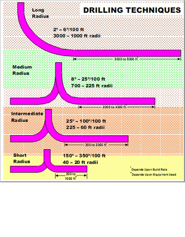
Deflection angel > 3o/100 ft

Angle of Deflection
in directional drilling, the angle at which a well diverts from vertical
usually expressed in degrees
In vertical, being zero.

Azimuth
in directional drilling, the direction of the wellbore or of the face of a deflection tool in degrees (0 -359 ) clockwise from true north.
an arc of the horizon measured between a fixed point (such as true north) and the vertical circle passing through the center of an object.
 Steering Tool
A directional survey instrument used in combination with a deflected downhole motor. It shows, on a rig floor monitor, the inclination and direction of a downhole sensing unit.
MWD+LWD
 
Systems and Coordinates
Depth Reference
Measured Depth (MD)
True Vertical Depth (TVD)
 
Inclination (Drift)
The angle (in degrees) between the local vertical (local gravity vector as indicated by a plumb bob) and the tangent to the well bore axis at a particular point.
By oilfield convention, 0° is vertical and 90° is horizontal.
 
Toolface
Rigsite use of the term toolface” is often used as a shortening of the phrase “toolface orientation”. This can be expressed as a direction from North or topside of the wellbore.
Toolface Orientation is the angular measurement of the toolface of a deflection tool with respect to either North or up (highside).
Highside/Magnetic Toolface
   —Highside Toolface 
indicates whether a component is facing up, down, to the left or right 
Magnetic Toolface 
an angular measurement from North

Mag TFO = Azimuth + Highside
Azimuth (Hole Direction)
the direction of the borehole on the horizontal plane, measured as a clockwise angle (0°- 360°) from the North reference.
All magnetic tools give readings referenced to Magnetic North; however, the final calculated coordinates are referenced to True North
Quadrant Bearings
the directions are expressed in degrees from 0°to 90° measured from North in the two Northern quadrants and from the South in the Southern quadrants, e.g., N87°E, S12°W, S90°W.
Direction Measurement
Azimuth Reference
Quadrant Bearings


read more "Directional Concepts"

Tuesday, March 13, 2012

Properties of mud

Properties of mud
 Plastic Viscosity (PV)
Control the magnitude of shear stress develops as one layer of fluid slides over another.
Measure of friction between layers.
Provides a scale of the fluid thickness.
Decreases with increasing temperature; with liquids; the reverse with gasses .
Effective viscosity depends on fluid velocity flow pattern, difficult to measure, but can be calculated.
PV is the difference between readings at 600 rpm and that at 300 rpm
A measure of the attractive forces between particles due to positive and negative charges
Measure the forces causes mud to gel in case of motionless
Shows a minimum level of stress must be provided before mud flows
Expressed in lb/lOOft2
A parameter of the Bingham plastic model. YP is the yield stress extrapolated to a shear rate of zero
It can be increased by Bentonite .
 Gel strength
Ability of mud to develop gel structure .
Defines the ability of mud to held solids and measures thixotropy
Is Determined using viscometer .
The sample stirred at high speed and the allowed to rest for 10 sec or 10 m.
The torque readings at 300 rpm is taken as gel strength at specified time.
Expressed in lb/100 ft2 .
Converted to metric by multiplying by 0.478 .
  Filtration and filter cake
Filtrate is the liquid that passes through the porous and permeable rock medium, leaving the cake on the medium .
A layer of solids deposited on the rock is described as filter cake
Loss occur when mud pressure is higher than formation pressure
Quantity of mud loss depends on volume of filtrate and thickness and strength of filter cake, and differential pressure .
Ideal mud gives small filter loss and thin and tough mud cake
 
Filtrate is a disadvantage due to formation damage & plugging pores by  shale swelling .
Mud cake is an advantage due to stabilizing the well bore  but when increasing it decreases the hole diameter
Polymers are used in mud cake .
Drilling muds are tested to determine filtration rate and filter-cake properties.
Cake properties such as cake thickness, toughness, slickness and permeability are important because the cake that forms on permeable zones in the wellbore can cause stuck pipe and other drilling problems.
Reduced oil and gas production can result from reservoir
     damage when a poor filter cake allows deep filtrate invasion.
Can be determined by filter press, called API filter press
  
pH of mud 
Describe the acidity or alkalinity of mud
Defined as the negative logarithm of the hydrogen ion (H)
Measured by pH meter or strips or dyes


read more "Properties of mud"

Emulsion mud

Emulsion mud
Water is a continuous (normal oil 5-10% by volume)
Formulated by using sodium soap as emulsifier
Oil is added to
 increase penetration rate:oil mud allows to drill faster than watermud
reduce filter loss,
improve lubricity,
reduce lost circulation
reduce torque and drag in directional well
The stability of emulsion mud is very important to insure best performance.
 The degree of stability of a certain emulsion can be measured by several observations. The resistance of an emulsion to conduct electric current (or the breakdown voltage) is one of the important measurements which determine emulsion stability. Also filtration loss and mud viscosity are often considered measures of mud stability.
 
The oil soluble polymers in a form of a gel, according to the instant invention, allow a good thermal stability and avoid any rheological contribution. They may be used at high temperature and high pressure conditions.

read more "Emulsion mud"

oil base mud

oil base mud
Water in oil emulsion
Diesel or crude oil forms its continuous phase
Sometimes called invert emulsion
Water droplets are emulsified in oil
Water is used for gel strength and barite content
Soaps are used as emulsifiers
Soups are made from monovalent ion (Na+) or divalent ion
(Ca++)
The soap molecule bridge together oil and water interfaces
Agitation is required to break the water into small droplets
Oil/water ratio determine the final properties
 
Oil-based muds generally use hydrocarbon oil as the main liquid component with other materials such as clays or colloidal asphalts added to provide the desired viscosity together with emulsifiers, polymers and other additives including weighting agents. Water may also be present, but in an amount not usually greater than 50 volume percent of the entire composition. If more than about 5% volume water is present, the mud is often referred to as an invert emulsion, i.e., water-in-oil emulsion
  

ADVANTAGES:

(1) performs all the functions of a water-base mud or permits an acceptable
substitute for these functions;
 (2) has most of the desirable properties of a water-base mud;
(3) does not hydrate and disperse cuttings;
(4) will not dissolve salt or other water-soluble formation deposits and can be
used to core such sections
(5)exhibits good penetration rates
 (6) protects productive horizons
 (7) does not increase the interstitial water of cores; and
 (8) is not affected by contaminants such as cement, anhydrite, salt or shale, and
can tolerate contamination with water and raw crude. 
 Higher oil water increases resistance to contamination and
temperature stability
Used to drill hole with severe stability
More stable at high temperature
An excellent to drill pay zone; reduce formation damage and
preserve original permeability

 Disadvantages:
 
• Contaminate the environment
• Flammability hazards
• Difficult removal of drilled solids due to high plastic PV 
• Difficult electric logging


read more "oil base mud"